fall inside a hole
Yuuenchi and Kiddie Land Repairs
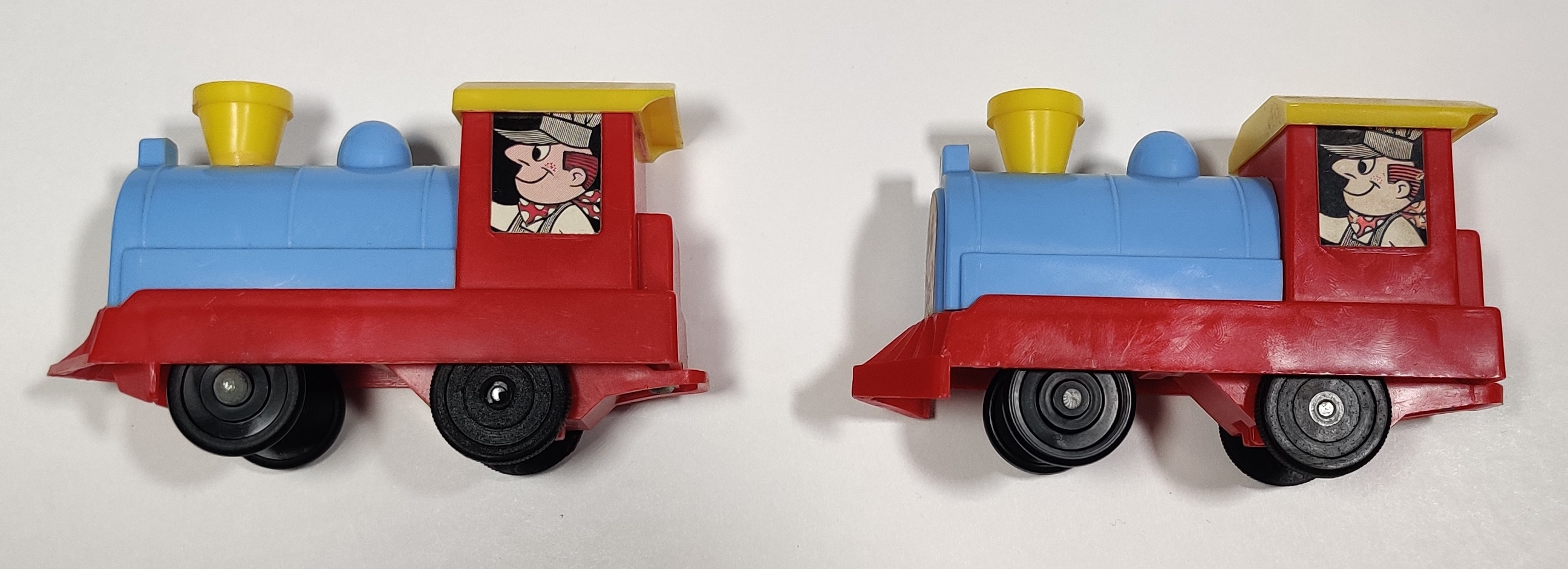
The Plarail Amusement Park Series (ゆうえんちシリーズ, Yuuenchi series) and the Child Guidance Kiddie Land were seemingly developed and produced jointly between Tomy and Child Guidance Toys in the late 1960s and early 1970s. The three moving accessories were released in the US and UK as Child Guidance Kiddie Land with red Child Guidance track and in Japan the accessories were available individually and in sets. The amusement park train was sold in a few other Child Guidance sets as well as individually as the "Joy Ride" train. In Japan a Disney themed version of the series was released as can be seen in the Plarail Museum and in the U.S. the Child Guidance version of the toy was adapted into a Disney World train playset in the 1970s.
Amusement park train repairs
The Japanese domestic releases of this locomotive seem to have been modified to be shorter to fit the Plarail loading gauge. Because of this, they have a different gearbox setup as well as a different power switch. The later Disney Plarail set uses the taller export version of the train. if I ever end up with an earlier Japanese issue Amusement Park train I will add details about repairing that version here.
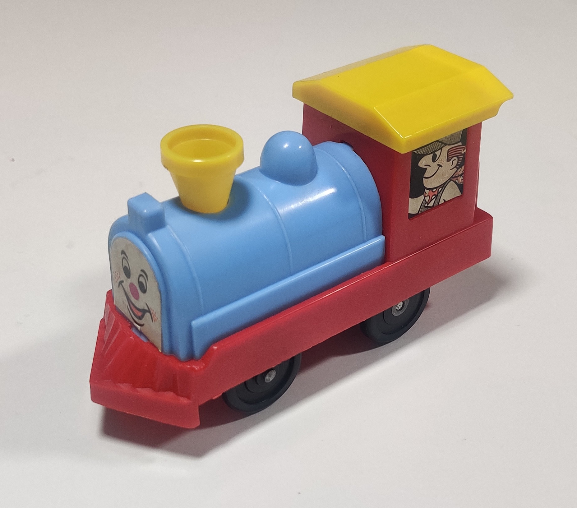
The red plastic used in the majority of the engine's construction is pretty brittle and can crack easily. Of my three amusement park engines only one is completely intact with both others having multiple cracks or chips in red plastic pieces. The battery compartment area and the red plastic gearbox carrier insert piece are both highly susceptible to damage, and cracked areas are often prone to cracking more.
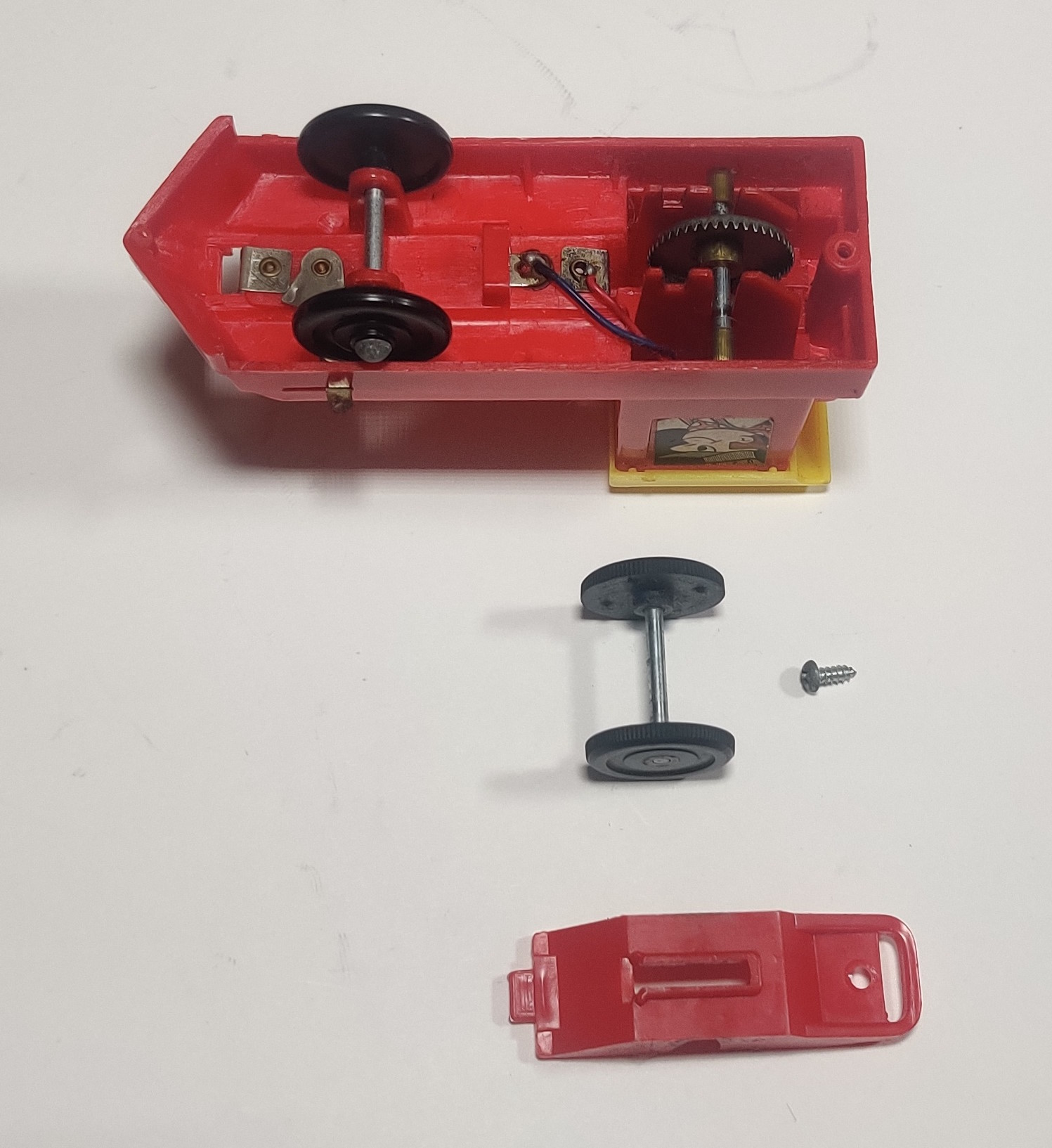
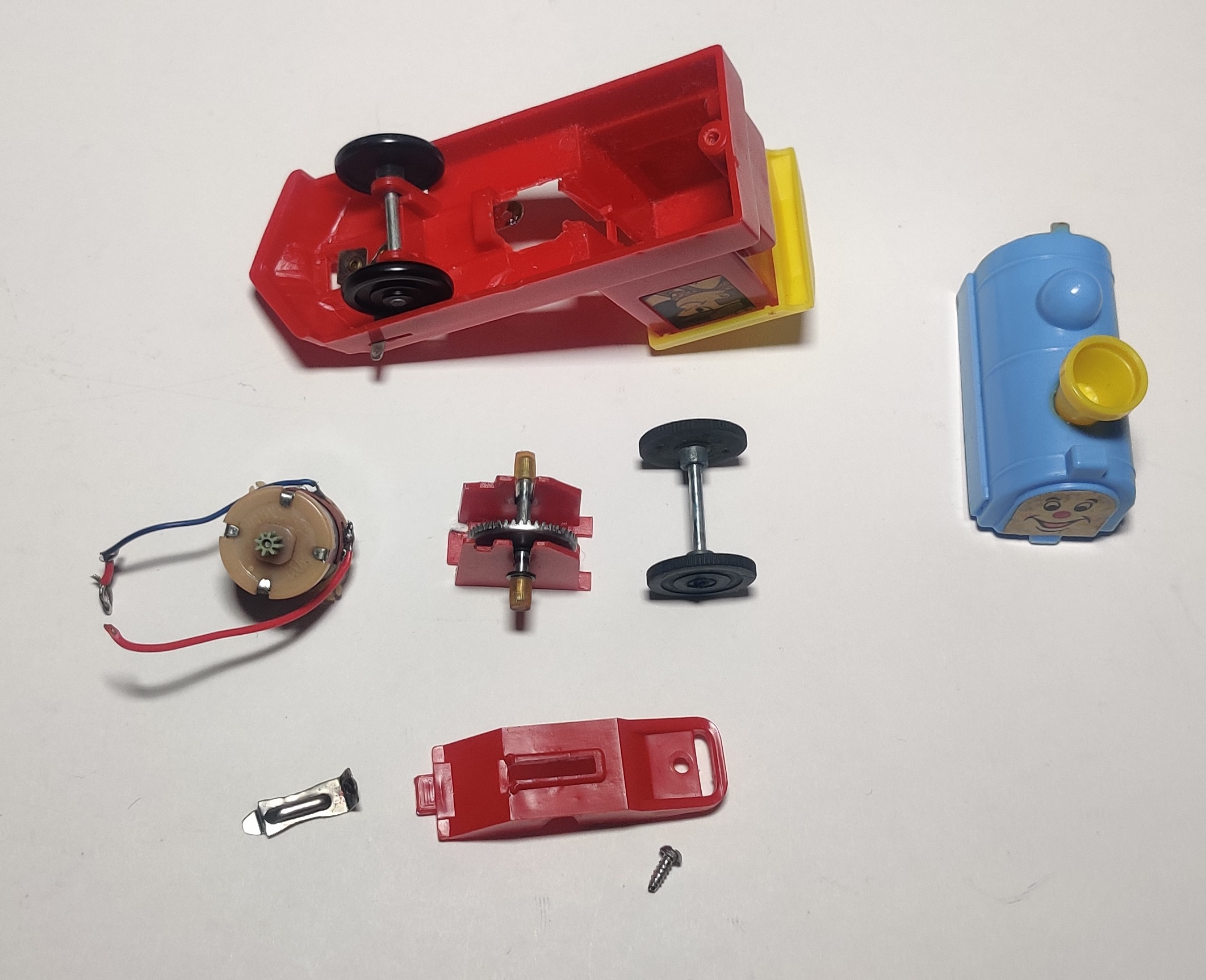
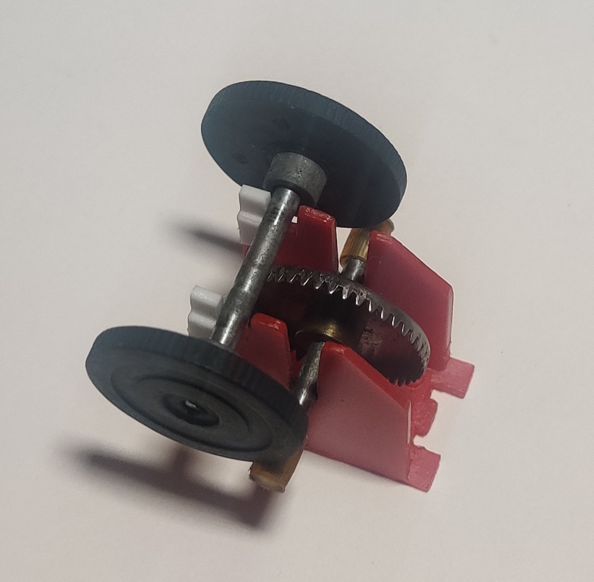
The gearboxes in these engines is somewhat odd. Some use a different larger motor than other Plarail engines at the time that transmits power to a large crown gear on the only shaft in the gearbox. The eight tooth pinion gear can split and may need to be replaced (the motor shaft is 2mm, so this gear is the same as many other components that use a 2mm inner diameter 8 tooth gear). One of my amusement park trains was found with a 9 tooth pinion gear, but this may or may not have been original. Another variant uses a smaller motor with a metal pinion gear. The second stage of the gearbox reduction just comes from the rim of the all-rubber drive wheels engaging with the much smaller slotted tubing on either end of the gearbox shaft.
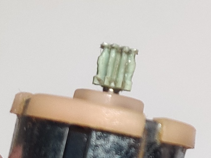
One of my engines came to me with this rather chewed up pinion gear which I ended up replacing as it was also split. I don't think I have seen such odd wear on such a small plastic gear before.
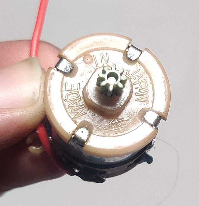
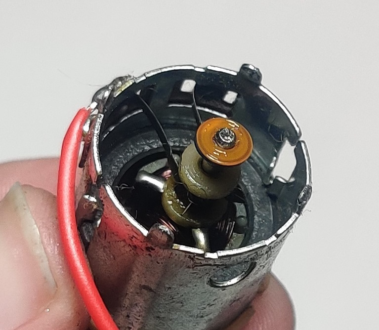
The top and bottom of the motor are held on with four tabs on both the large and small motor variants. If you need to clean the brushes or commutator or otherwise service the inside of the motor removing both the top and bottom makes it easier to remove the entire rotor.
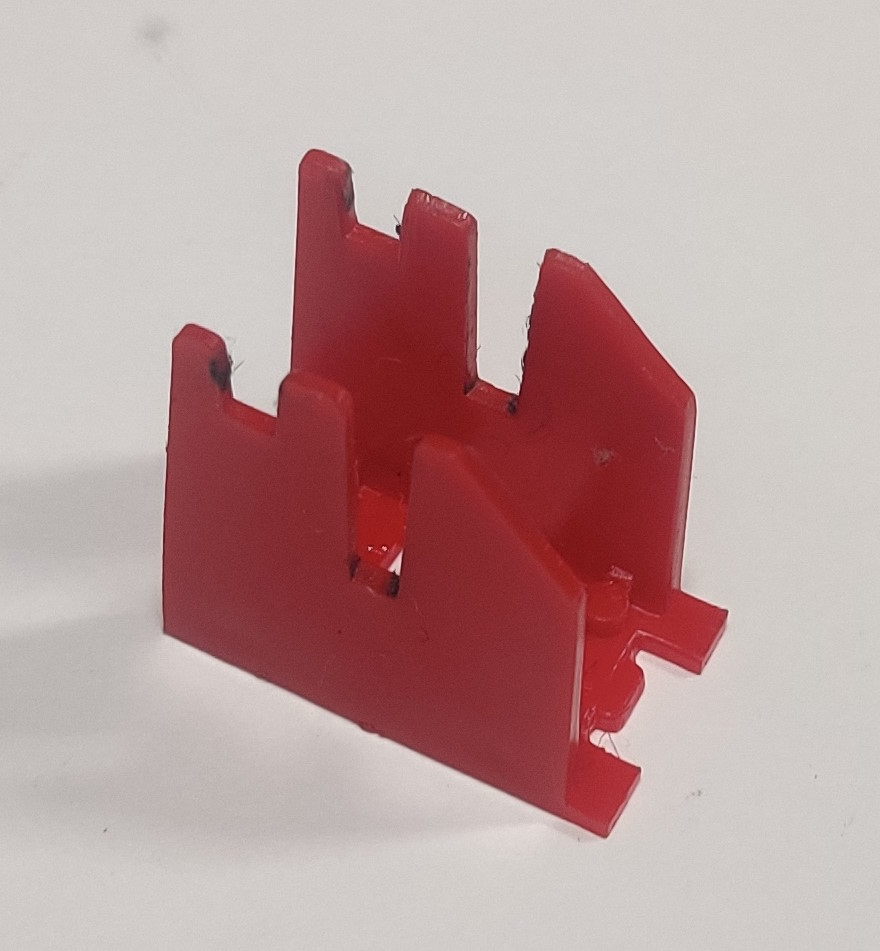
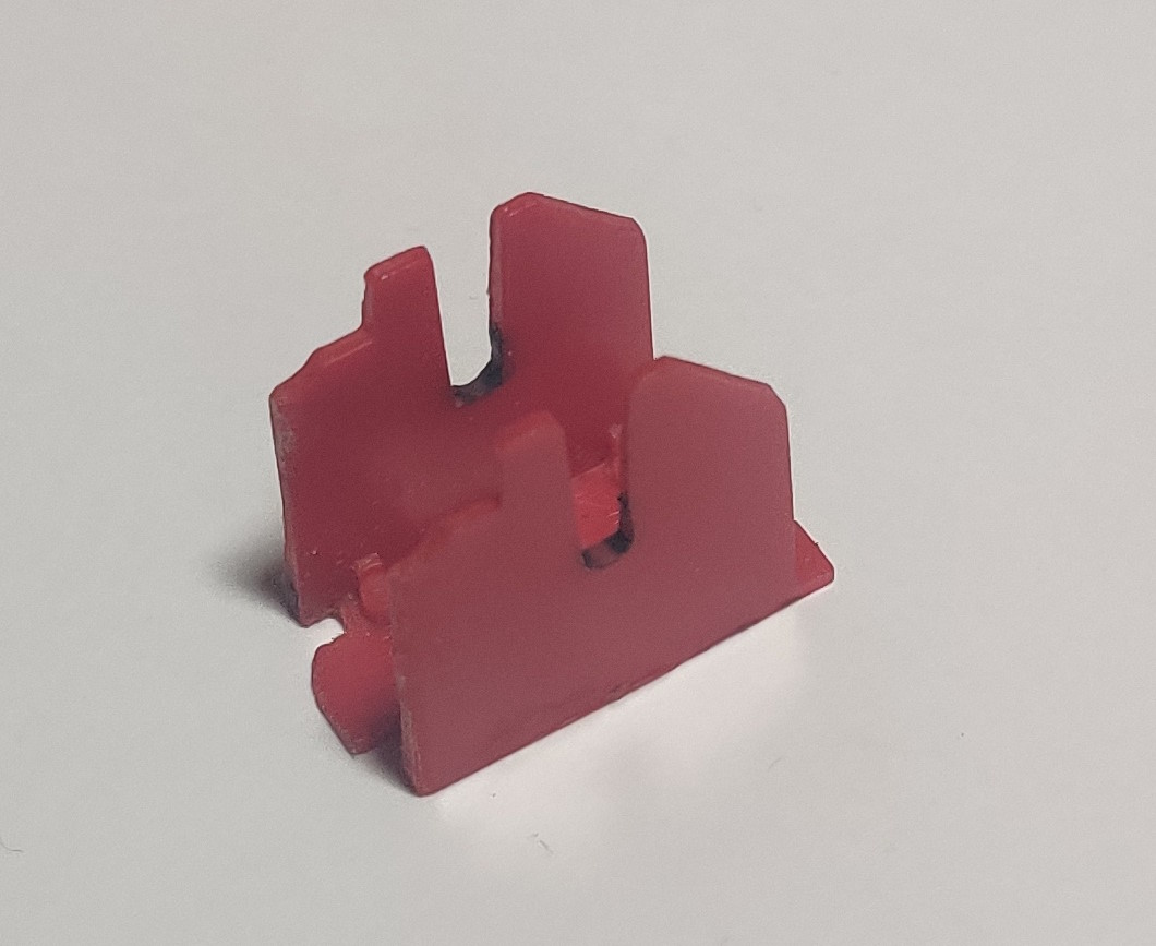
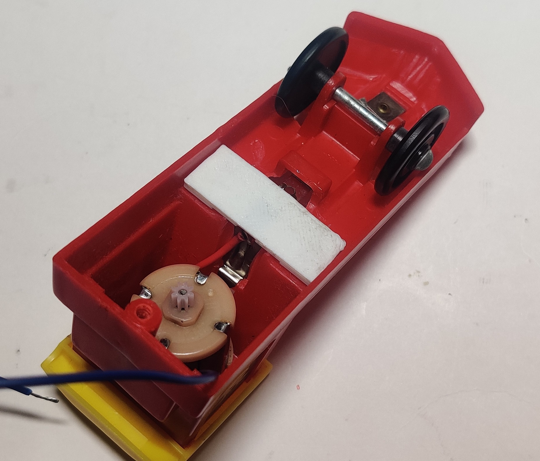
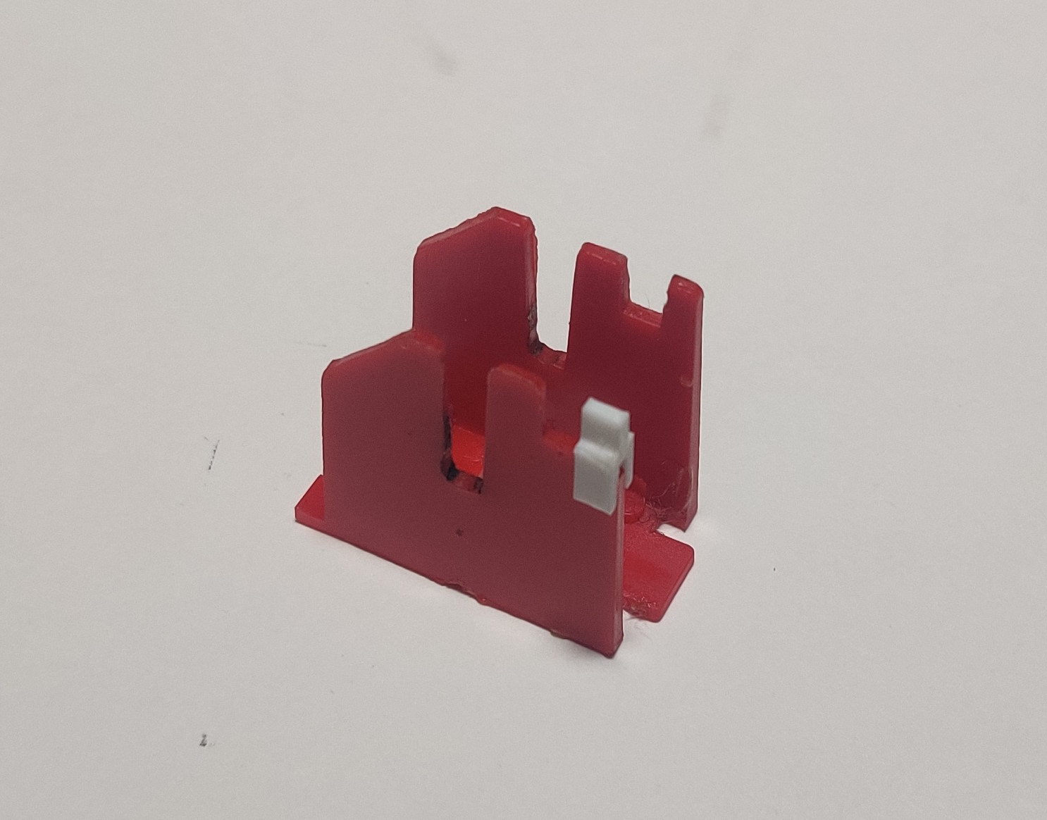
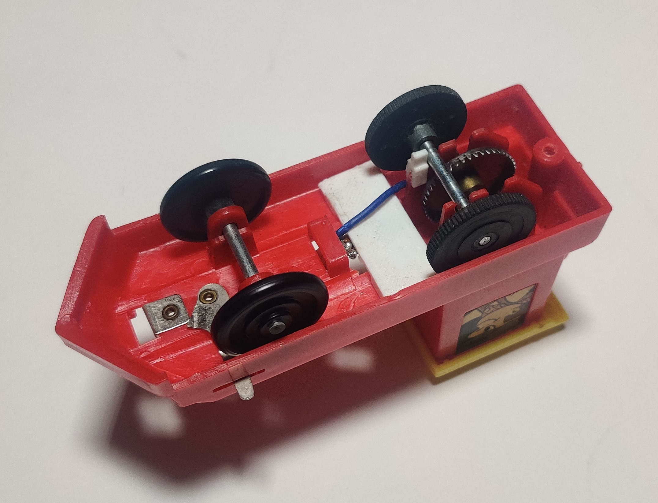
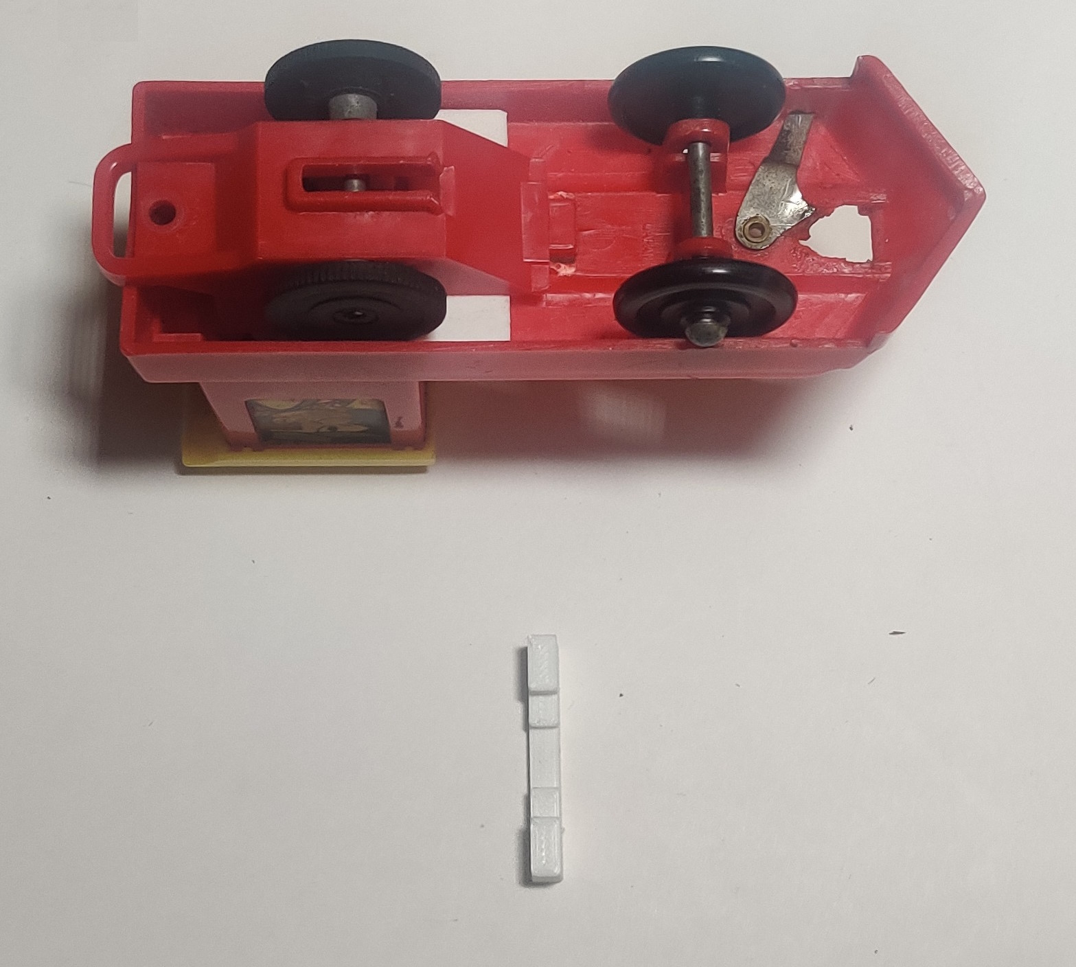
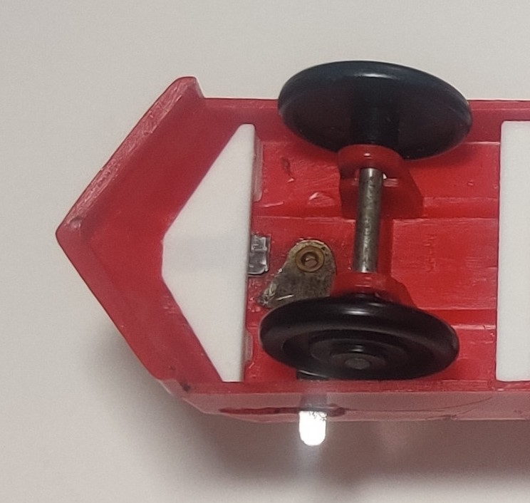
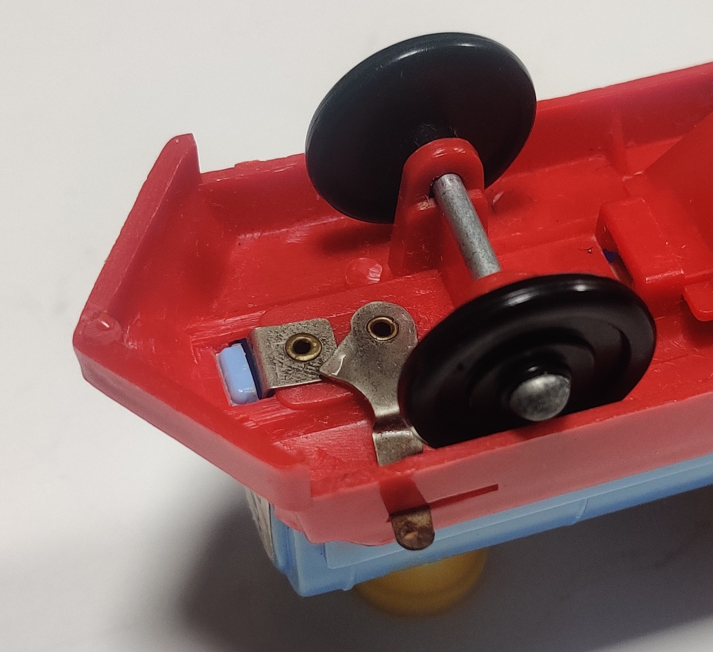
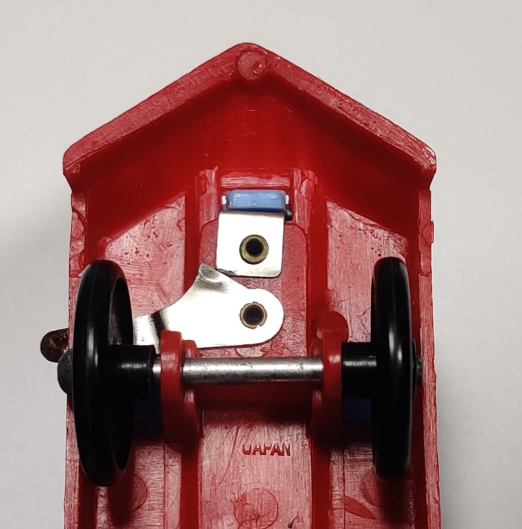
The motor, shaft, and wheels are all held in place by this carrier piece. The square hole in the base of the piece sits around the square molded into the face of the motor around the output shaft and holds the motor in place against the roof of the locomotive. The deeper slots hold the gearbox shaft and large contrate gear and the shallower slots hold the rear wheels which are in turn held in place by the bottom bracket which includes the activation tab. If either (or both) of the front "clips" that help form the shallower slot are broken than the wheels will want to ride further forward than intended and not make as good of contact with the rubber tubing on the gearbox shaft. Usually this means the train will not properly run the amusement park accessories. I replaced broken clips on two of my engines with these small replacements that can be glued in place on the carrier.
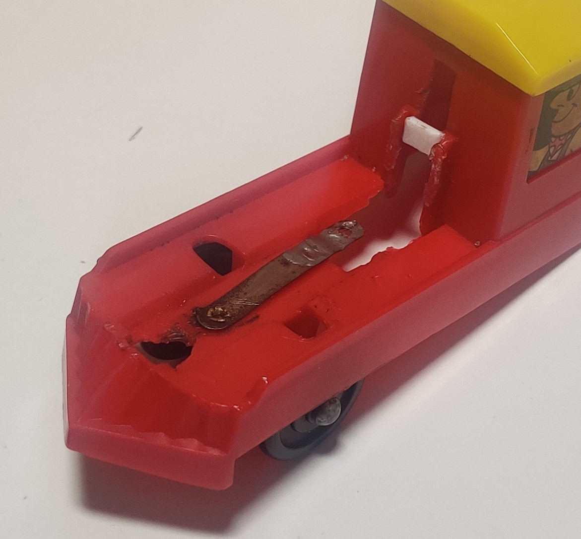
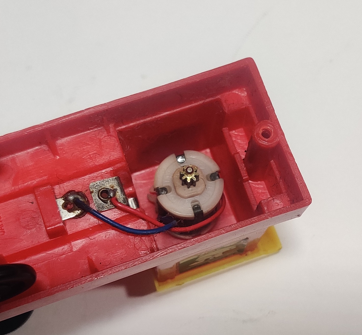
All of these small rivets holding battery contacts into place are potential places where the chassis will want to split apart.
Two of my engines were broken up around the positive battery contact. One was loose from its wire and the chassis while the other had been repaired at some point previously with what looks like part of an off-the-shelf C battery holder. I also had to replace the support towards the top of the battery contact slot on one engine but I just did this with some cutoff from a scrap 3D print instead of a new print.
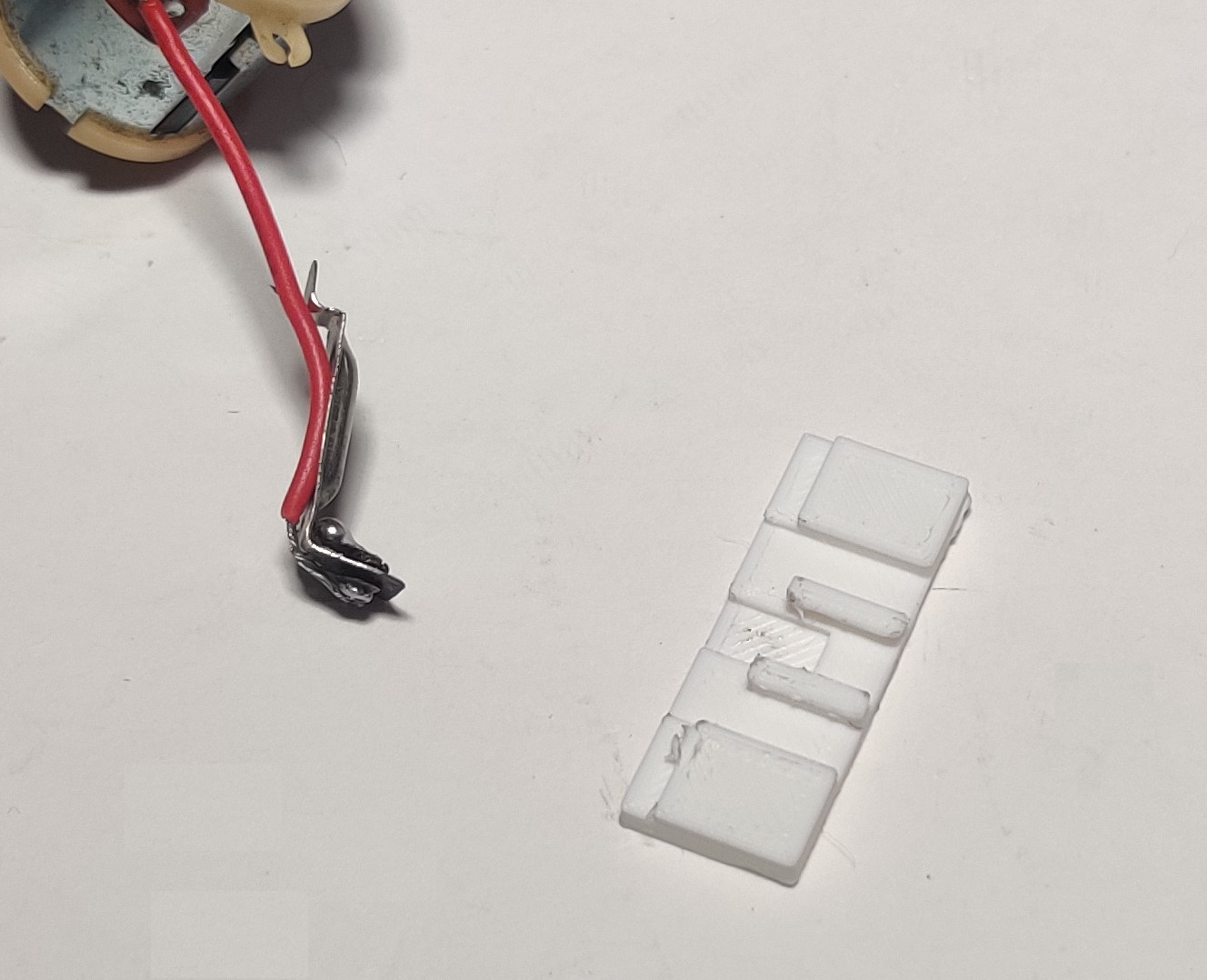
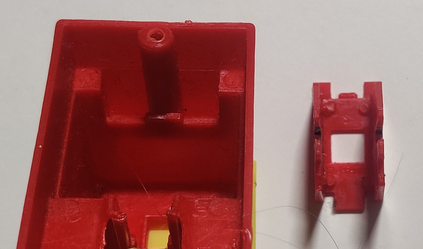
To replace the positive contact area towards the rear of the engine I designed this carrier plate which the original battery contact can slide into. A replacement contact that is the same approximate width and thickness should also work.
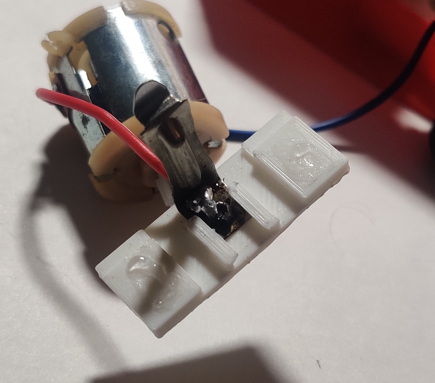
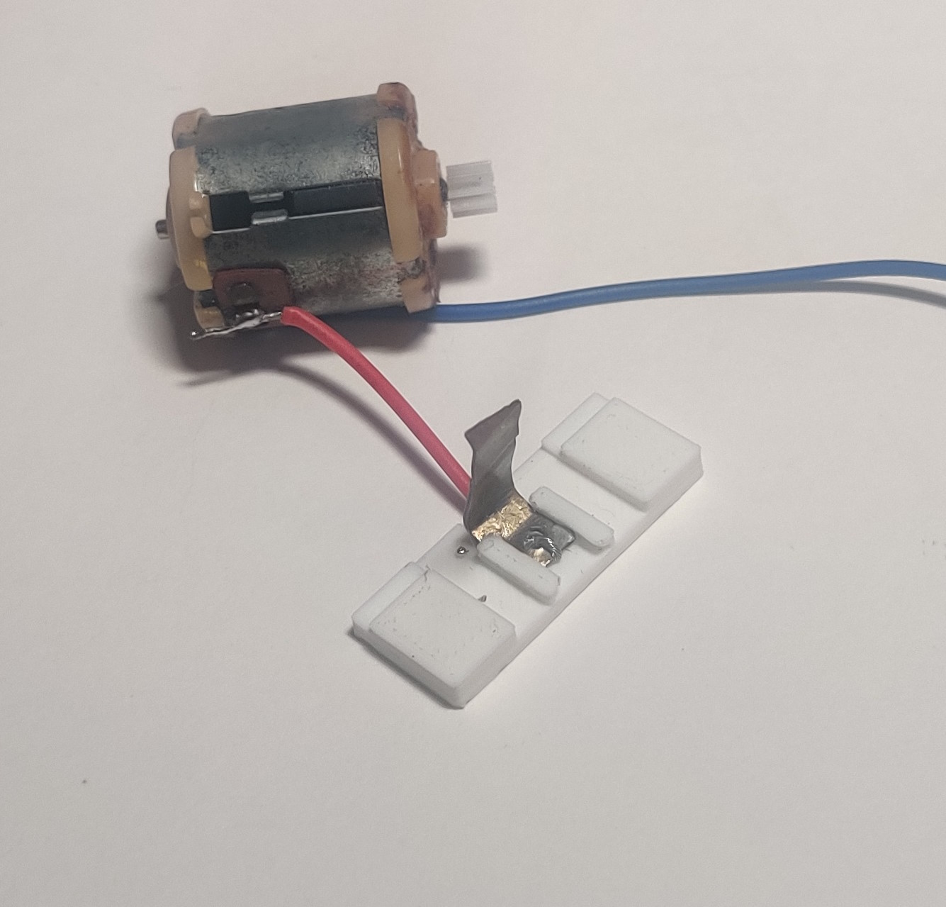
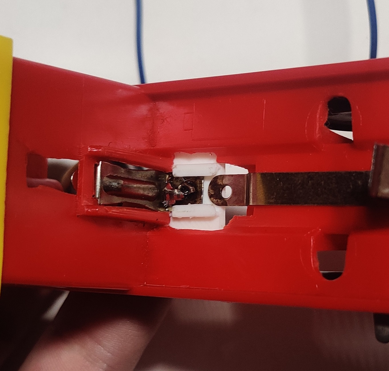
After any broken wires have been replaced or resoldered and the motor is in place in the cab the carrier plate is then glued into place on the sturdier parts of the chassis with the upper part of the contact correctly engaging with the body shell. Now is also a good time to solder the other motor wire back on if it was removed earlier. The newer version of the contact carrier plate being shorter also makes resoldering to the contact strip easier with the carrier already installed. The current version of this clip has additional parts cut out to help prevent the wheels from rubbing against this clip.
This is more or less a one way process and makes the positive battery contact difficult to remove, but the same is true of the original riveted design. From here the rest of the gearbox and chassis can be reassembled. The earlier version of the carrier plate that sticks out forward further actually interferes slightly with the bottom clip, so I shortened it for the current version. A better version of the clip may also hold the loose end of the contact strip going down the length of the chassis but doing this without getting in the way of the bottom clip or wire soldered to the contact strip might be tricky. The rear side of the clip has also been cut down in the current version to prevent it from fouling on the rear wheels - the section that supports the contact should be lined up with the edge of the motor cavity like the entire larger carrier plate shown above is.
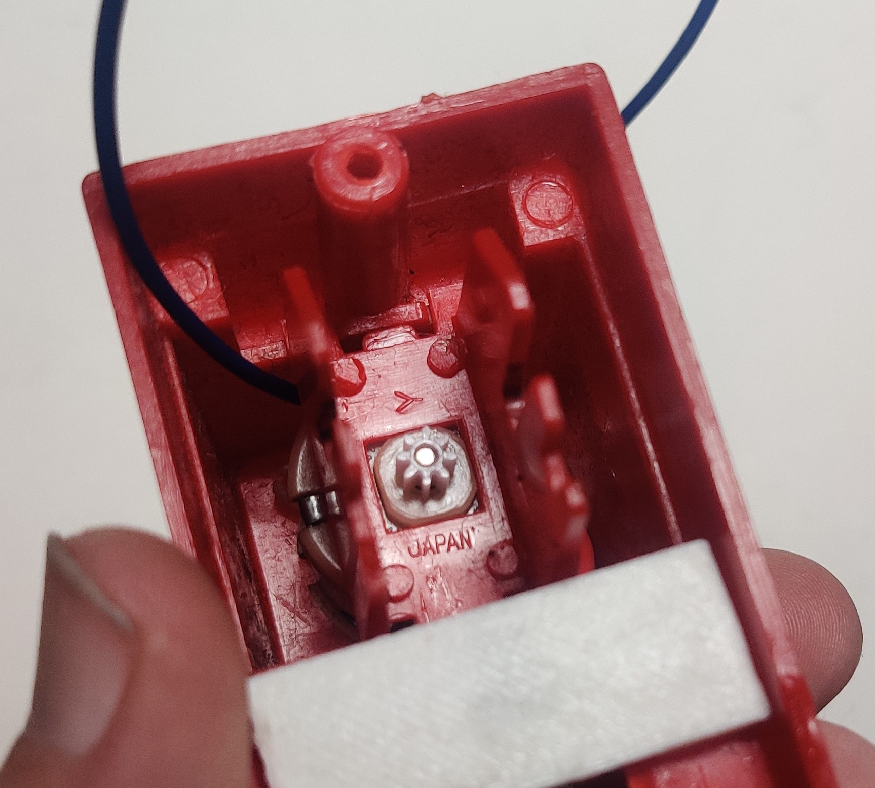
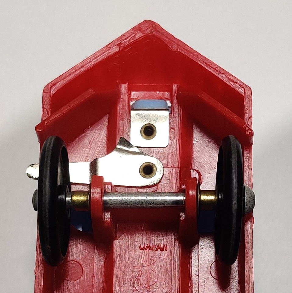
The gearbox carrier plate is installed with the protruding end facing forward and the indented end facing the rear and straddling the screw post. The square molding on the top of the motor should fit into the square cutout in the carrier. If any of the short tabs on the inner end of the carrier plate are broken off they should be replaced with the clip shown above.
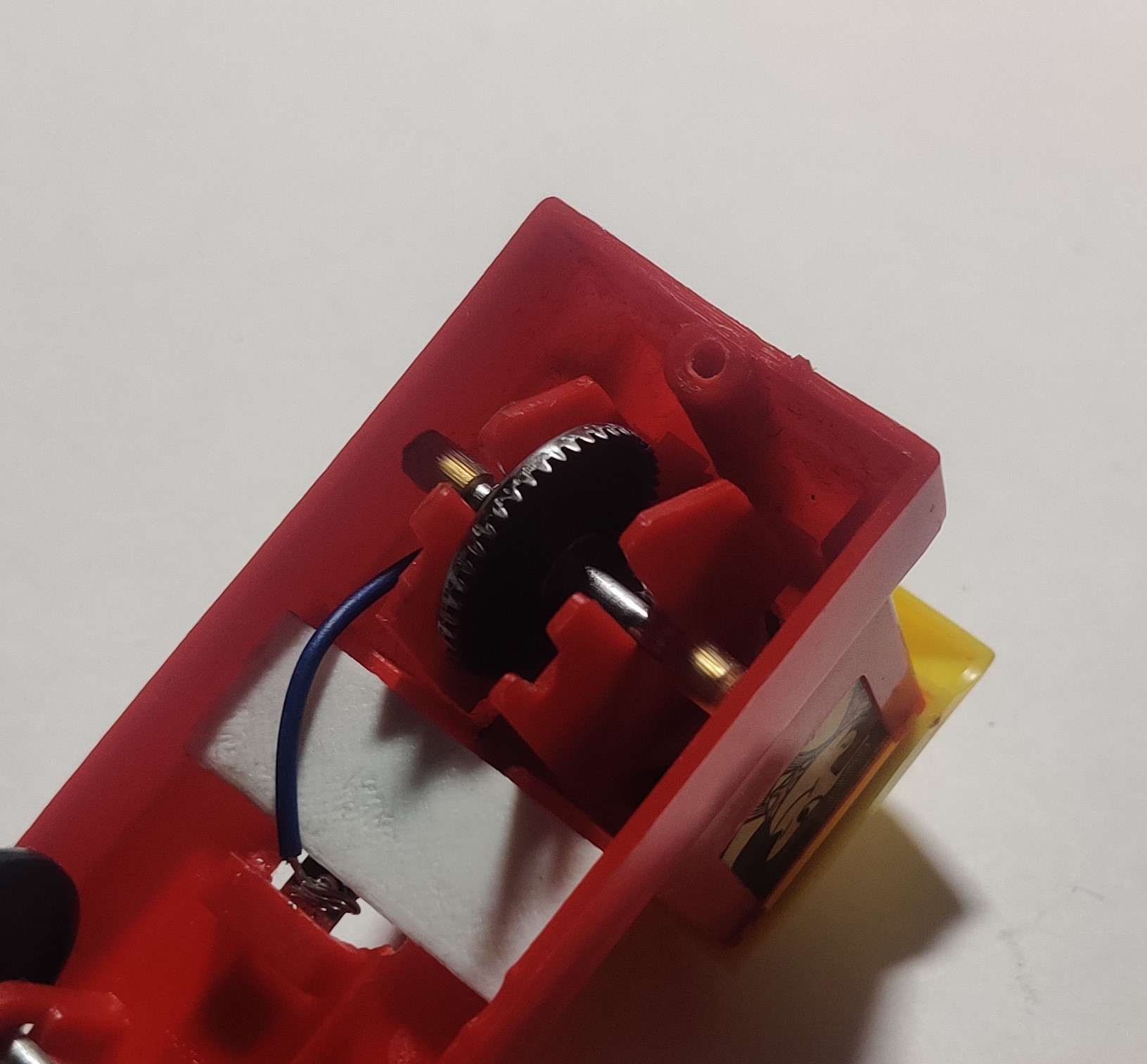
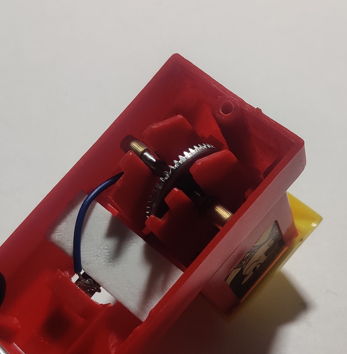
The "correct" way for the contrate gear to be installed from what I have seen is offset to the left when looking at the bottom of the locomotive but if the motor is rewired in backwards this gear can be installed to the right to reverse the direction of the output shaft and make the engine still run in the forwards direction. Note that one of the front protrusions that holds the rear wheels in place is broken off - this was later replaced as shown above.
The wheels and lower bracket can then be reinstalled.
If the plastic clip on the bottom that the activation tab bracket sits in it broken it can be cut down and replaced with another 3D printed bracket that can be glued onto the bottom of the chassis. If the rear screw post is broken it can also be cut and filed away and replaced with another 3D printed bracket. The hole may need to be adjusted slightly depending on what screw is used (the engine I had to replace it on did not have the original screw).
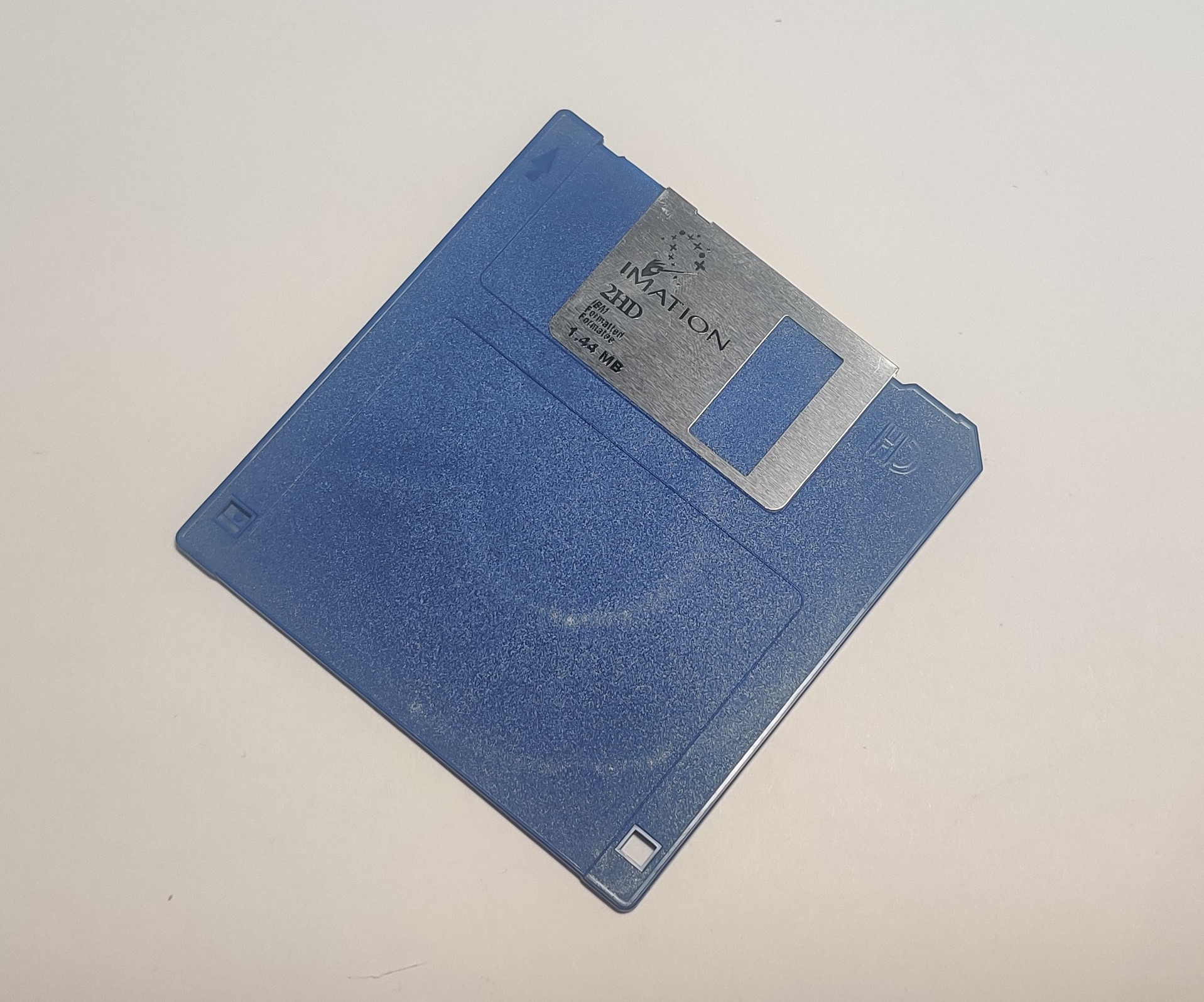
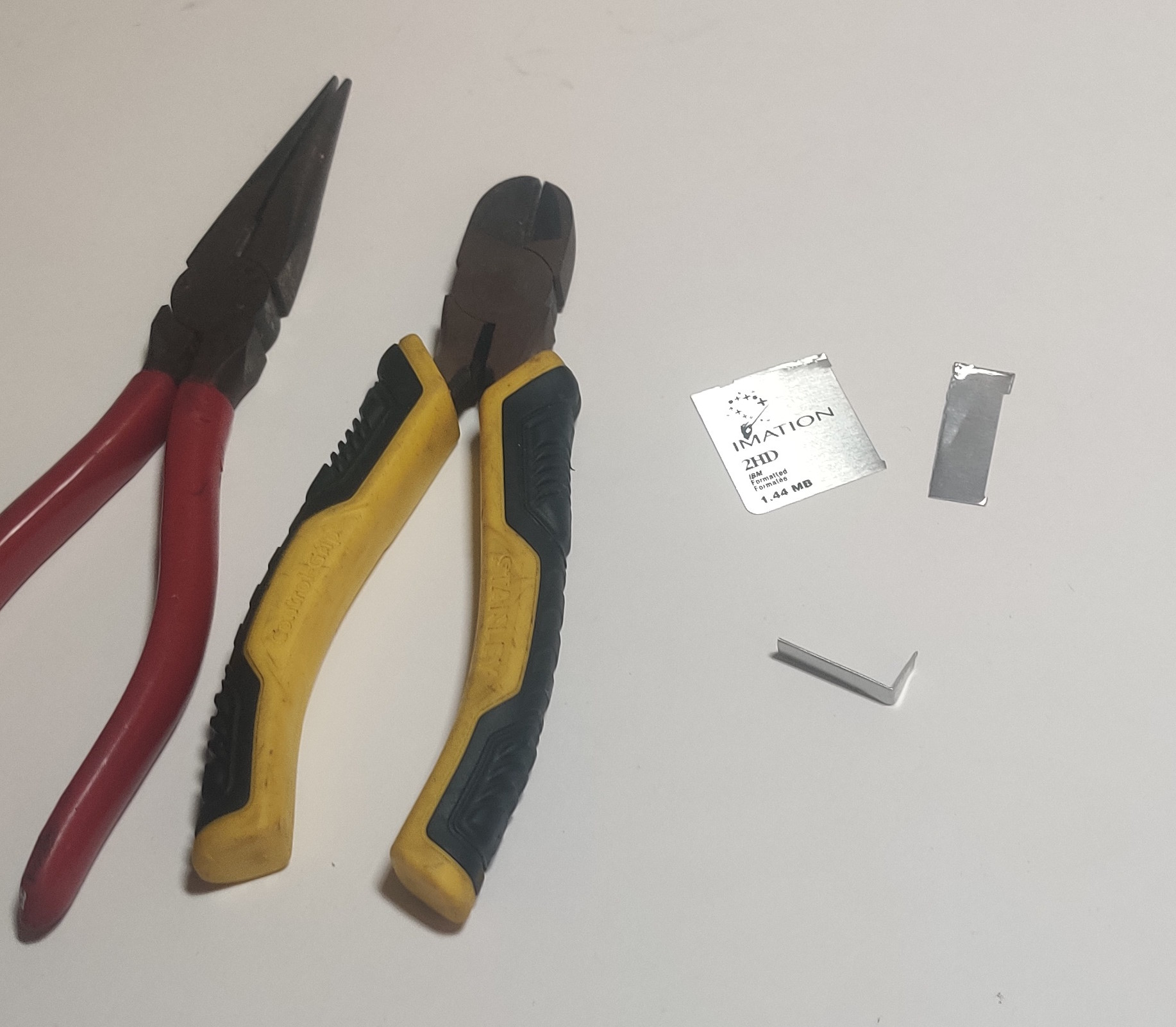
To replace a missing front contact I cut up the shutter of a 3.5" floppy disk. I would like to make replacement battery contacts out of some aluminum strips that are the same thickness as the original.
Another 3D printable bracket in the front of the locomotive holds the front contact in place. Because of the way that the front power switch is supposed to work, double check that the motor runs and the switch stays in place when turned on, and bend the front battery contact as needed to get it to operate properly.
(November 9, 2023)
I have recently acquired a slightly different Child Guidance Kiddieland train that has a different molding in this front area. This version of the bracket will not work correctly with these engines. It seems this was an earlier and somewhat short-lived design.
Stop track repairs
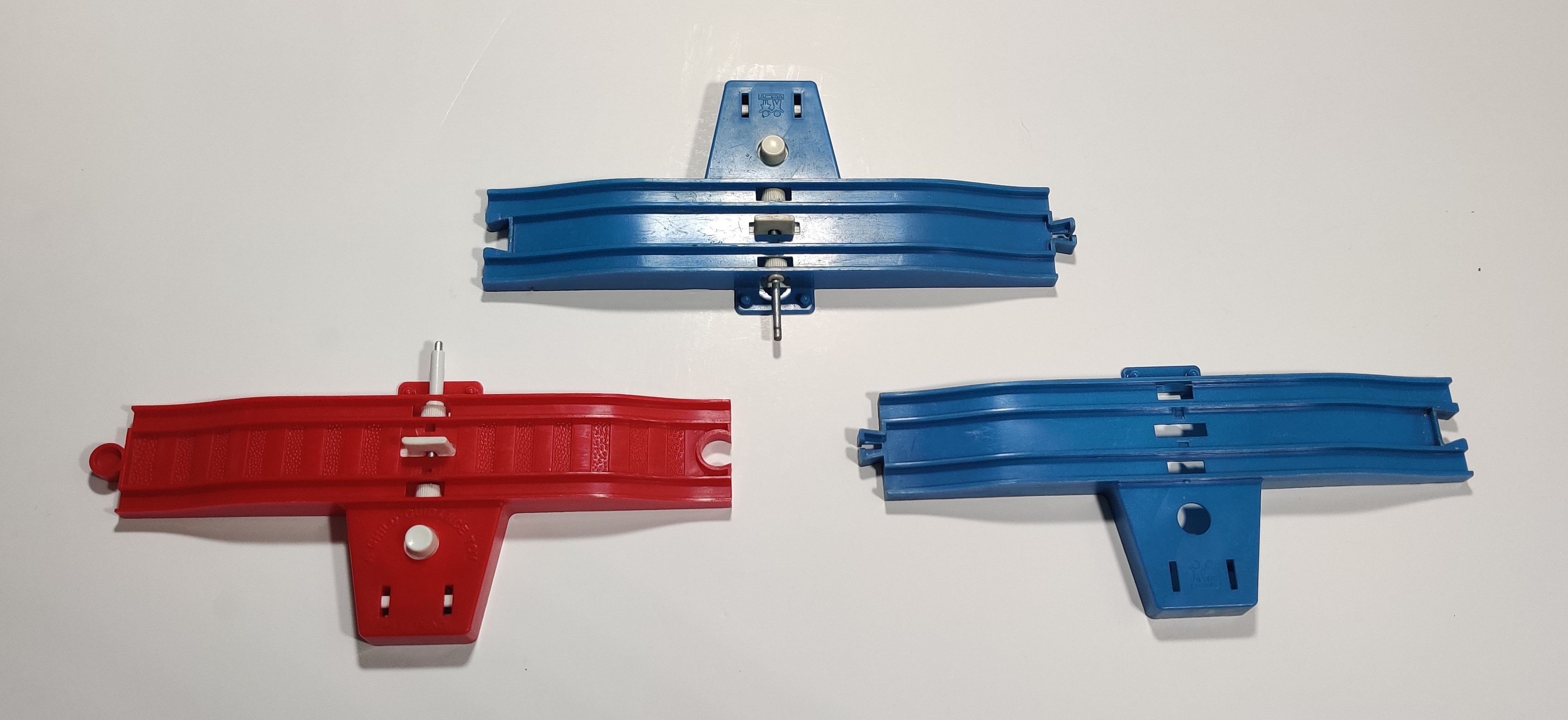
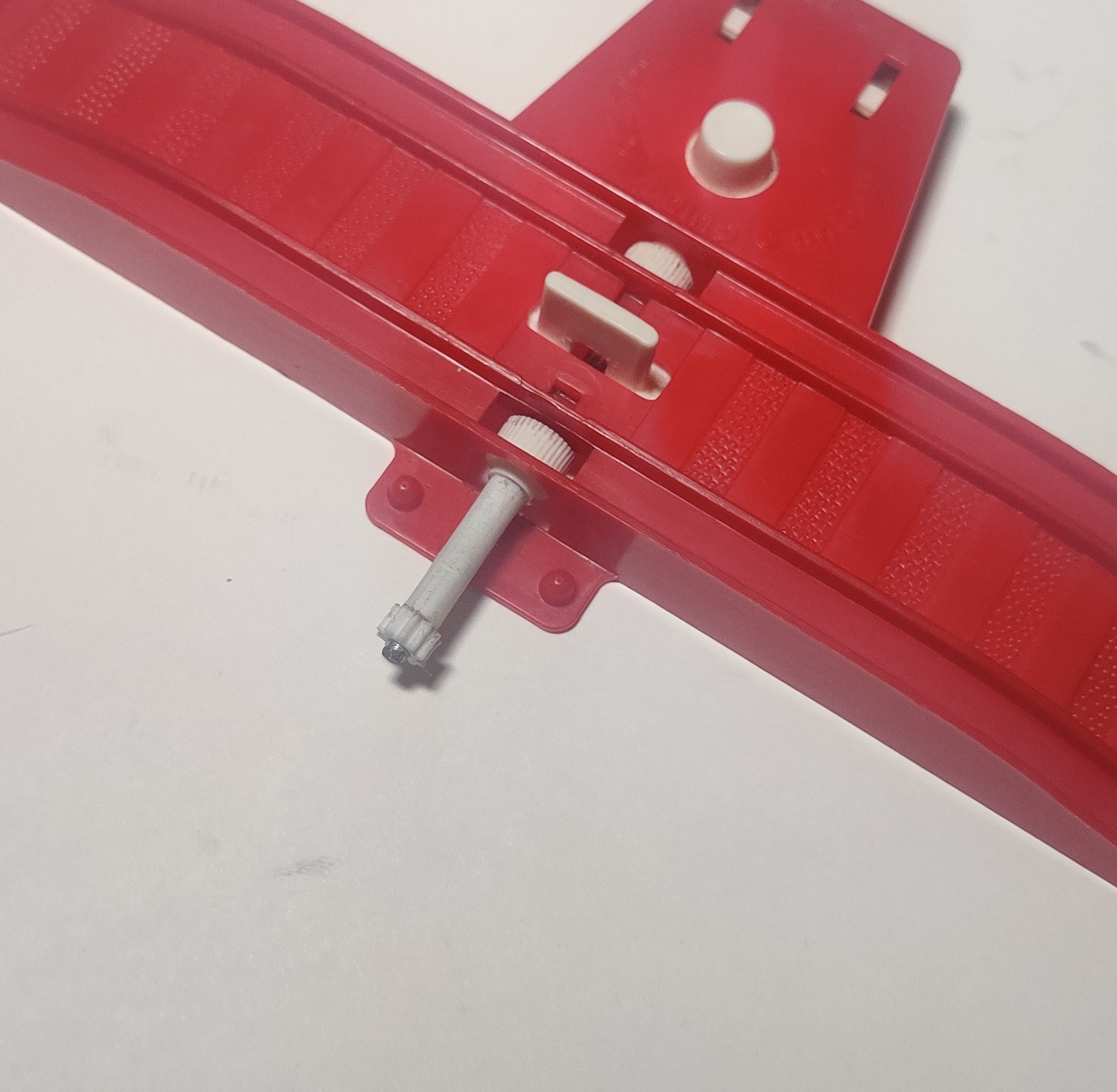
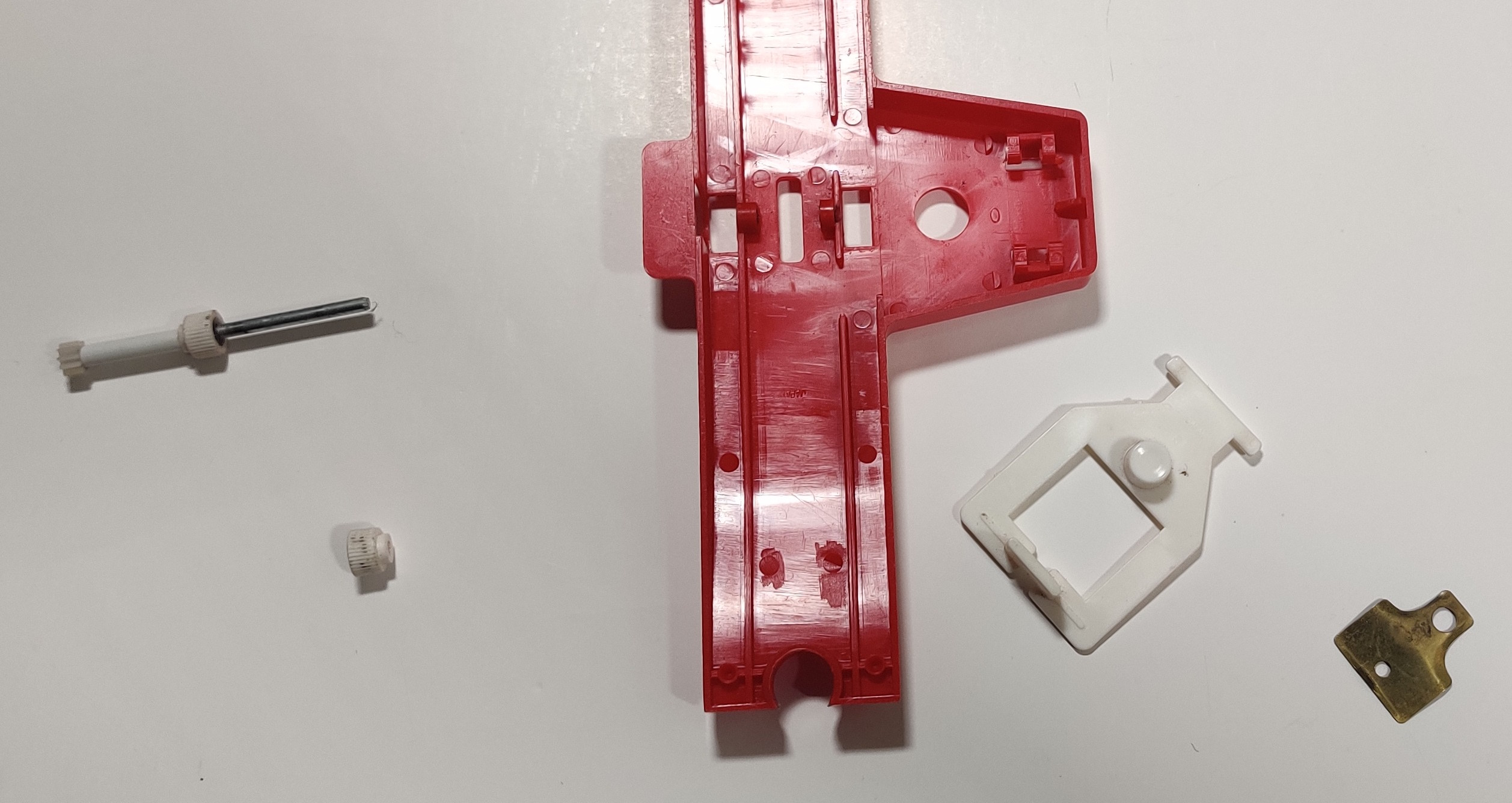
The accessories all fit over the same track sections which have a simple rim-drive pickup and activation tab stopper. Over time the gear on the end of the rim-drive mechanism splits and the track pieces are often found missing the end gear, plastic spacer, both, or even more components of this mechanism. The shaft in the track pieces is 3mm in diameter and the gear on the end has ten teeth. A 20mm spacer covers the rest of the exposed drive shaft, although this is not strictly necessary for operation.
The shaft is friction fit inside the two wheel pickups and the ten tooth gear. Pulling the outermost wheel pickup off the shaft will allow it to be pulled out of the molding on the bottom of the track.
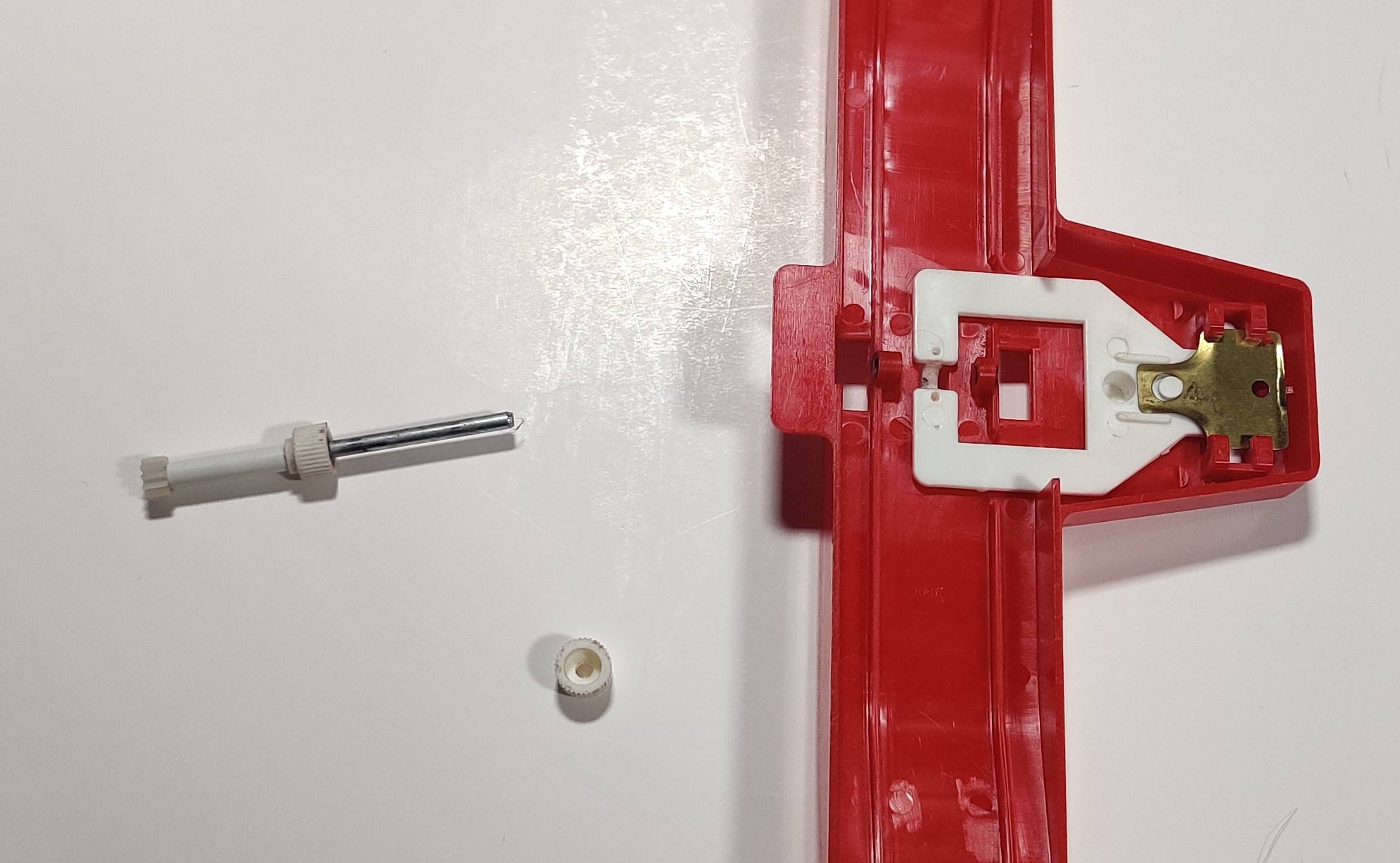
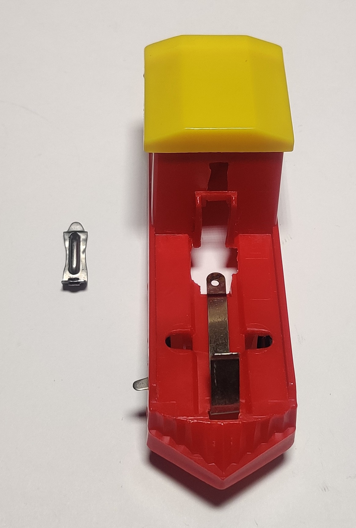
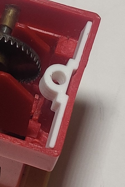
The spring in the stop rail is provided by this thin sheet of what looks like brass which springs the activation tab back into place when the button is released.
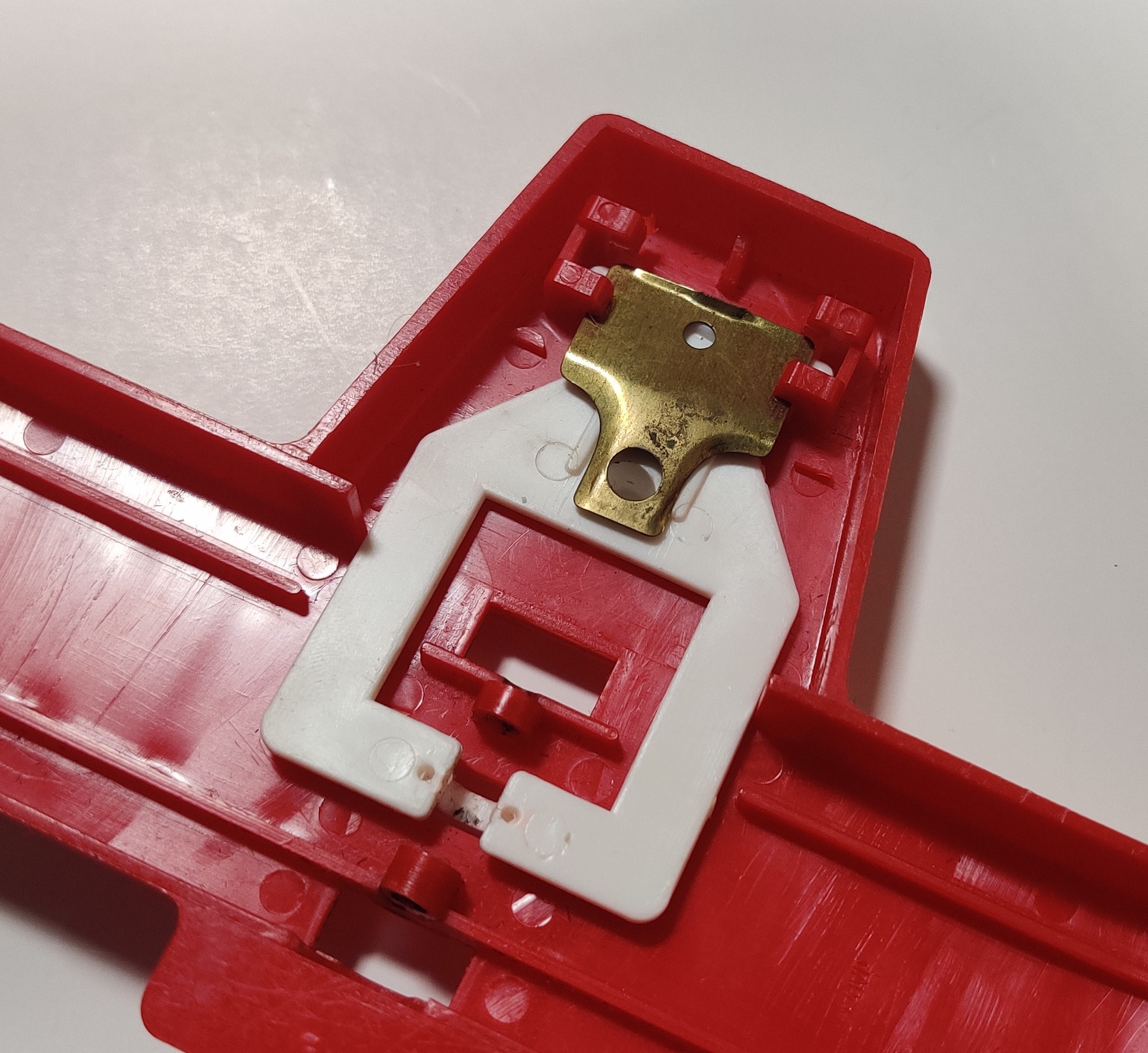
Lifting part of the protruding section up and over the molding of the white activation tab lever allows it to be pulled out of the molding if needed. I removed the switch in the Child Guidance stop rail pictured to repair a harder to find Plarail stop rail. These rails were seemingly made in the same Japanese factory and use the same components other than the main piece of rail itself.
As linked above I 3D printed some replacement gears and spacers. The spacers are dead simple and do not really need to be 3D printed (nor used at all, strictly) while the gears work in a pinch but not nearly as nicely as injection molded gears. A resin printer would probably do a better job.